A decorative LED frame
Here is a small personal project to brighten my home made from a cheap IKEA photo frame, and Arduino and a multicolor “NeoPixel” LEDs strip. The goal is simple: to realize a matrix of 12×10 big square pixels able to emit light in any color, and controllable from a smartphone. A simple demo video will explain the principle better (the LED flicker is due to the video and not normally visible): The video shows different working modes of the frame: clock, random pixels, gradual color change, sliding message. It is obviously possible to invent many other modes. Here are pictures of the frame:
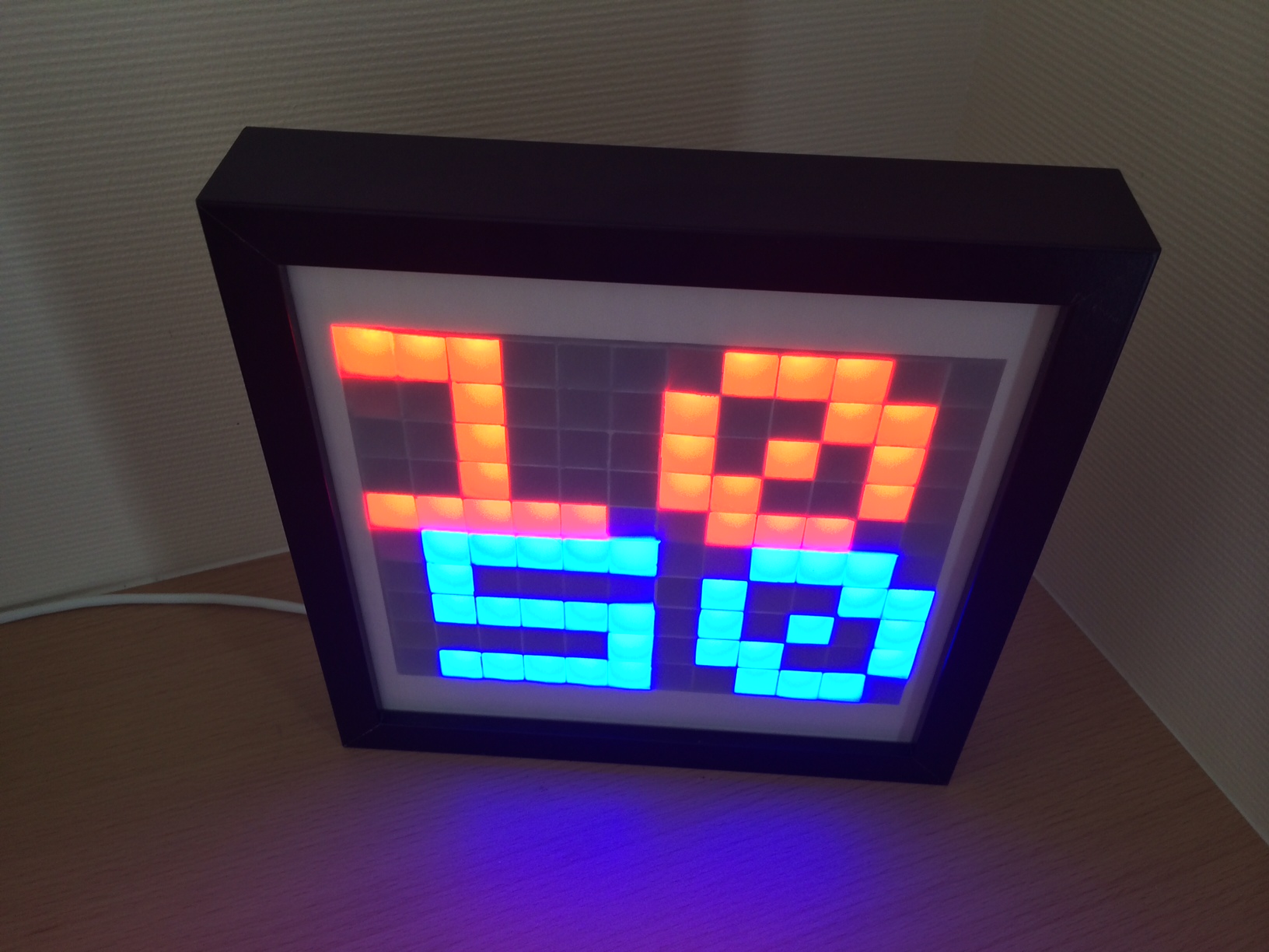
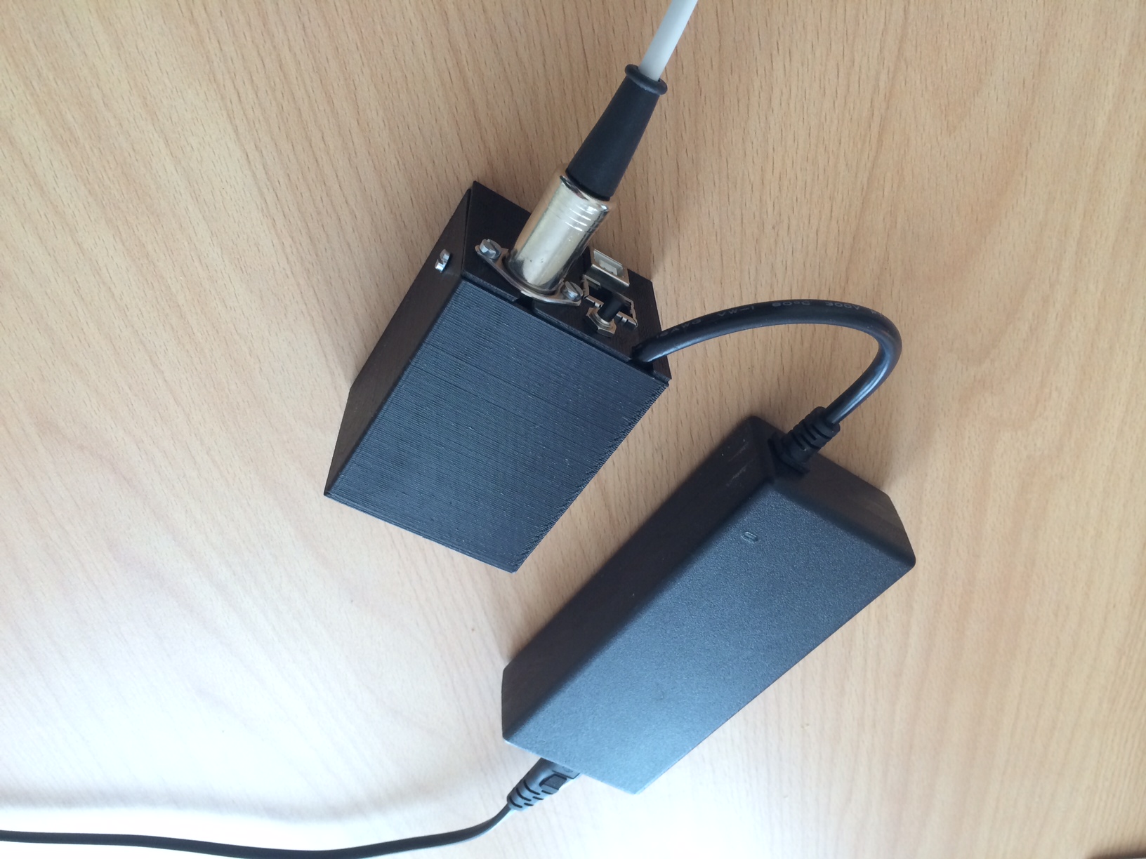
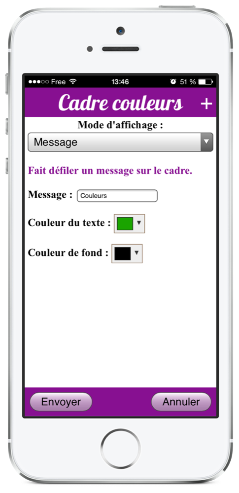
The first picture shows the frame itself, with the white cable used to power the LEDs and to control them. The second image shows the power supply and the control circuit. The white cable attached to the frame can be seen. The last image shows the application used to control the frame from a smartphone. Let’s now see how this frame is built.
Material
Let me list what I used to build the frame :
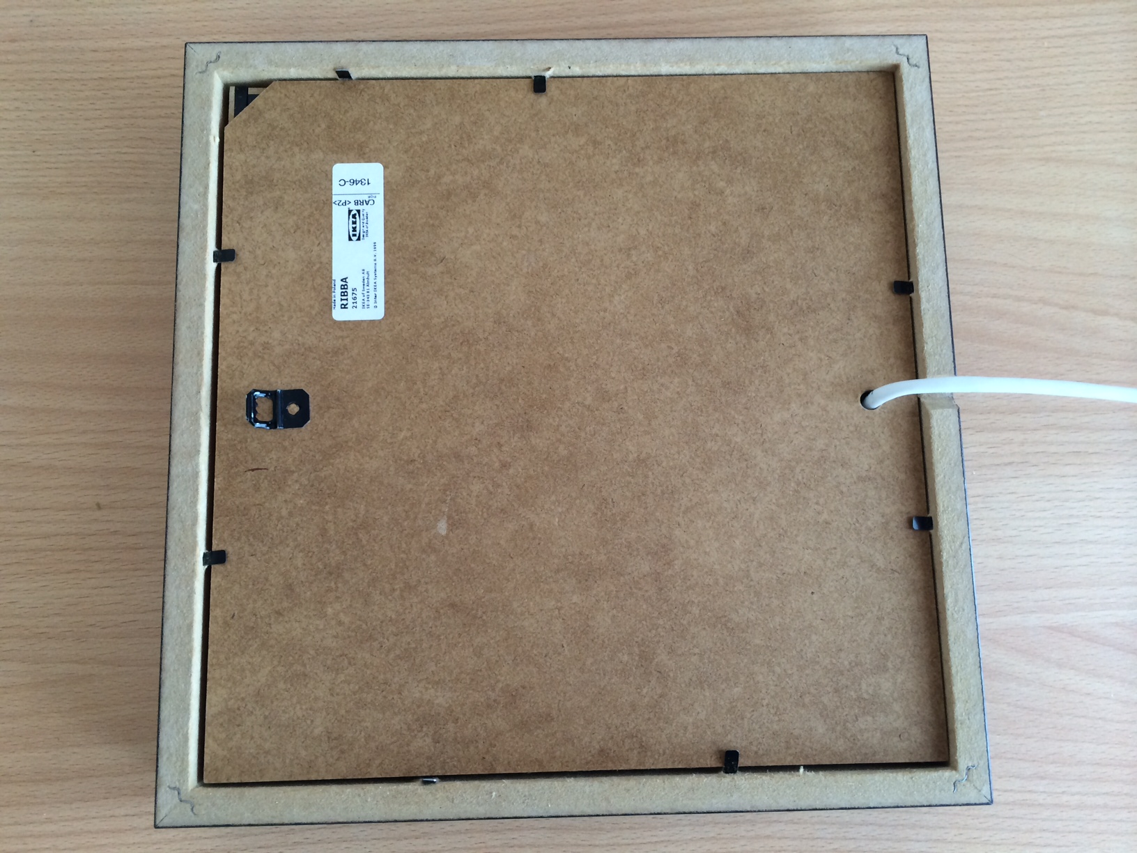
- a cheap IKEA photo frame made for a 23x23cm image, and deep of 4.5cm;
- an Adafruit Neopixel LED strip of 2m with 120 RGB (multicolor) LEDs that can be controlled individually;
- a sheet of tracing paper (23×23 cm at least) to diffuse the light;
- one Arduino Uno to control the strip;
- one Ethernet shield to connect the frame to the local network;
- a 5V 10A power supply to power the strip;
- a 4700μF capacitor to protect the circuit;
- a 5V 10A relay to control the strip power;
- a diode to protect the relay;
- a MOSFET N STP16NF06 transistor to manage the relay;
- a push button to ask the frame to display its IP address;
- a protoboard to soldier all components;
- a 2,5m cable with at least 3 big enough wires to put a distance between the controller and the display;
- a 5-pin DIN to plug the display into the controller;
- an M3 10mm screw and a nut to close the control box;
- black ABS plastic for the control box and the square pixels;
- some white spray paint for the pixels grid;
- a DS1307+ real-time clock to remember the time and the state of the frame;
- a 0.033MHz 12.5pF quartz to rhythm the clock;
- a lithium CR2032 battery to power the clock when the frame is unplugged;
- two 2.2kΩ resistors to connect the clock to the Arduino (pull-up).
I also needed some tools, found at the Téléfab (FabLab of Télécom Bretagne): drill, file, screwdriver, soldering station and 3D printer. I used OpenSCAD to design the plastic parts.
The display
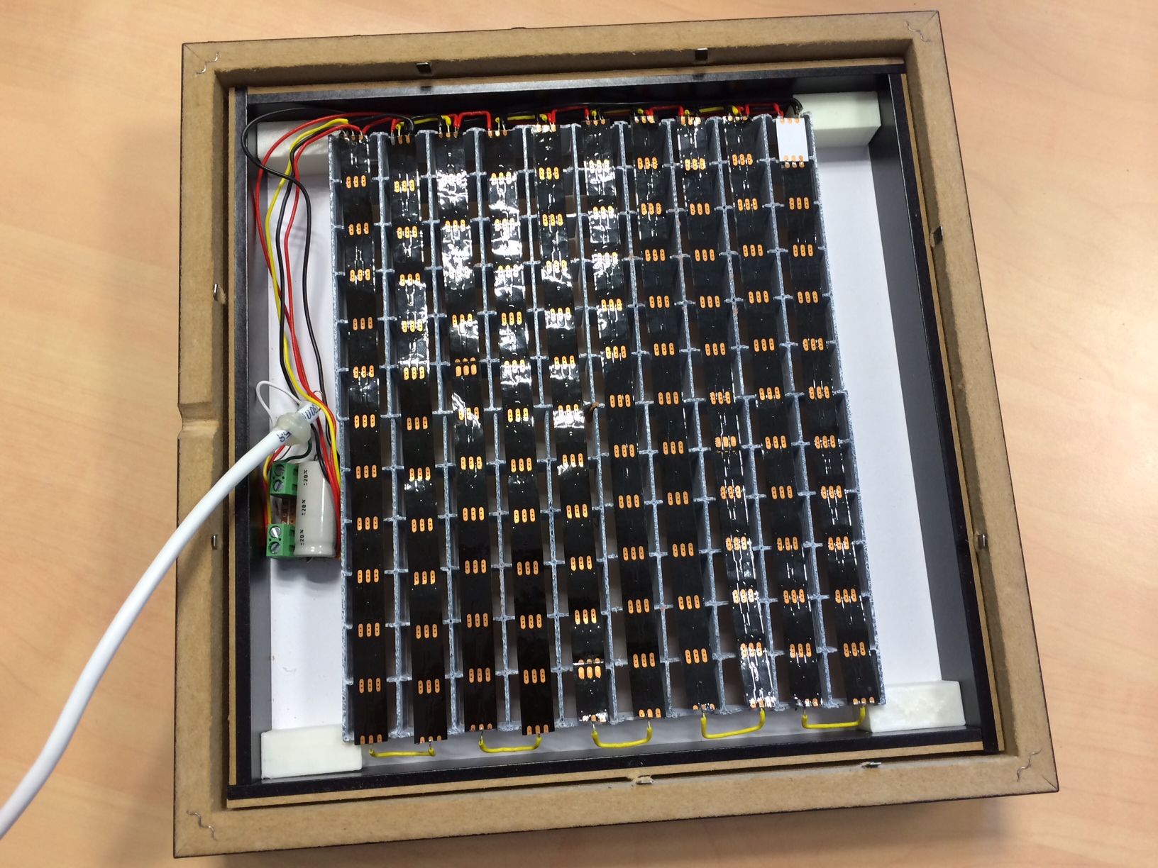
To realize the display, I started by modifying the LED strip. This strip is interesting because each LED contains a small control chip, which allows to chain a large number of LEDs with only 3 wires: ground, 5V and the control signal. Only one Arduino pin is used to control the whole strip, thanks to a library provided by Adafruit. Another interest of the strip is that each LED can be cut and soldered again to build different shapes, in our case a LED matrix. The best would be to fill the frame with pixels as big as possible, but that would mean cutting each pixel and soldering it again with the right spacing. To avoid that, I decided to use the spacing between two LEDs (120 / 200 = 0.6cm) as pixel size. This way, I can put a 12×10 LED matrix in the frame, with some spacing around it. So I cut the strip into 10 bits of 12 LEDs and soldered them again in a matrix shape. The power wires are connected only on one side to shorten the path between the power supply and each LED. The control signal has to be always connected in the right direction, so it has to be connected in an S shape. Here is the result: 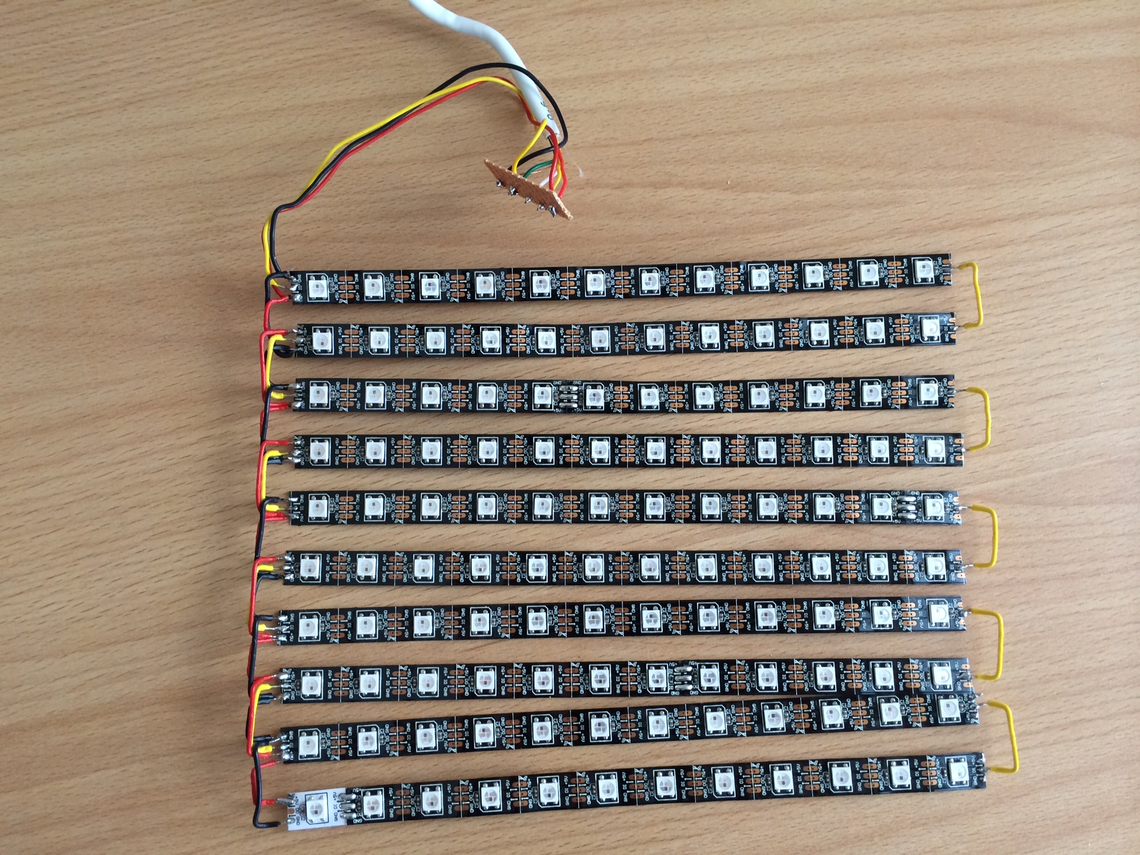
It can be useful to test sometimes that the strip is still working, using the Arduino and the example provided with the NeoPixel library.
Now the matrix is done, but pixels are not square. To change that, I printed a plastic grid using the 3D printer. All 3D parts are available on Github. As the grid is big, I first divided it into 4 parts to assemble. But an imperfect assembly left space for the light to shine between the parts. So I ended up printing the grid in one part on an Asimov 3D printer with a 20x20cm build surface at the fabriques du ponant. I printed black parts and then painted them in white. I had first tried printing them in black but the grid was overly transparent. The grid has some space to put the strip, but it may be necessary to file where the soldier is. I also attempted to cut the grid into white 1.1mm cardboard with a laser cutter (SVG file generated by the Python script with the same name). The result was very clean but the cardboard is a bit overly transparent.
To block the gird inside the frame, I designed a spacer (holder file) to print 4 times. To hide wires and empty spaces, I cut into the provided white cardboard a square of the size of the grid. To assemble, put everything inside the frame in this order:
- the wooden frame, visible side down;
- the provided glass;
- the tracing paper cut at the right size ;
- the white cardboard with the cut square ;
- the plastic grid and spacers.
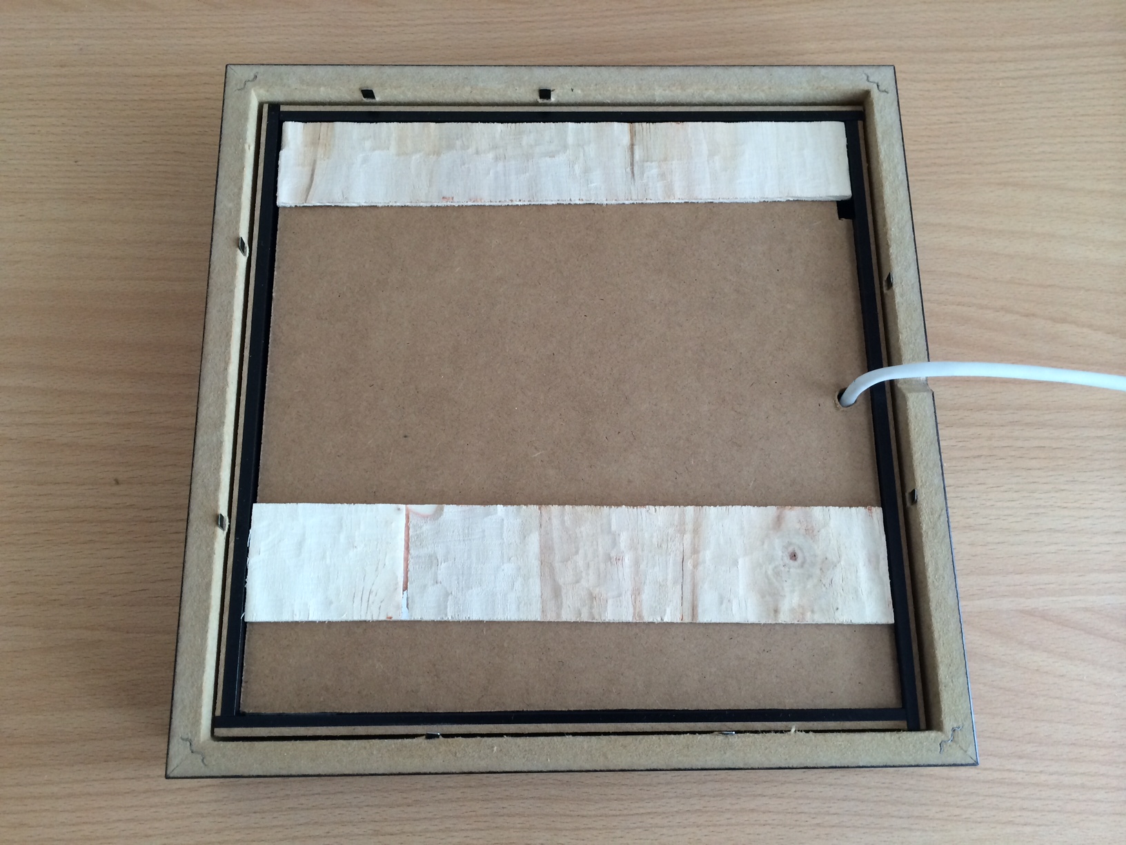
Here is the result :  The tracing paper is used to diffuse the light, otherwise pixels would not appear square. I tried using normal paper but the light was overly attenuated. I also tried using a plastic diffusion film, but the warmth from the LEDs damaged it. To let the control cable get out, a hole has to be drilled (middle down) inside the two sheets that close the frame. Then there is just to put the LED matrix over the grid and to close everything (first the small sheet inside the frame, and then the big sheet over it). It should hold by itself. It may be needed to add some small pieces of wood between the sheets if some space remains:
The display is over! Let’s now start the controller.
The controller
The controller is used to drive the LED strip. It includes the Arduino Uno and the Ethernet shield, and it is connected to the display through the control cable. It also icludes an RTC clock with a small battery to keep the time and save the state of the frame when it is unplugged. The battery should last more than 10 years. In addition to the clock, the circuit includes a relay that is used to cut the strip power when it is not used. This allows to reduce the power consumption (0.19A with the power cut compared to 0.5A with the LEDs set to black) and to avoid useless wear of the strip. As the relay requires an intensity higher than one Arduino pin can provide, it is controlled through a MOSFET N transistor. The diode in parallel to the relay coil avoid overloads when the relay is switched. The circuit is realized on a protoboard used as a shield over the Ethernet shield. Here is the electronic drawing:  It is quite simple. A 5-pin female DIN connector is used to connect the display. Le male connector is soldiered to the control cable (make sure you use the same pins). Here is the result :
 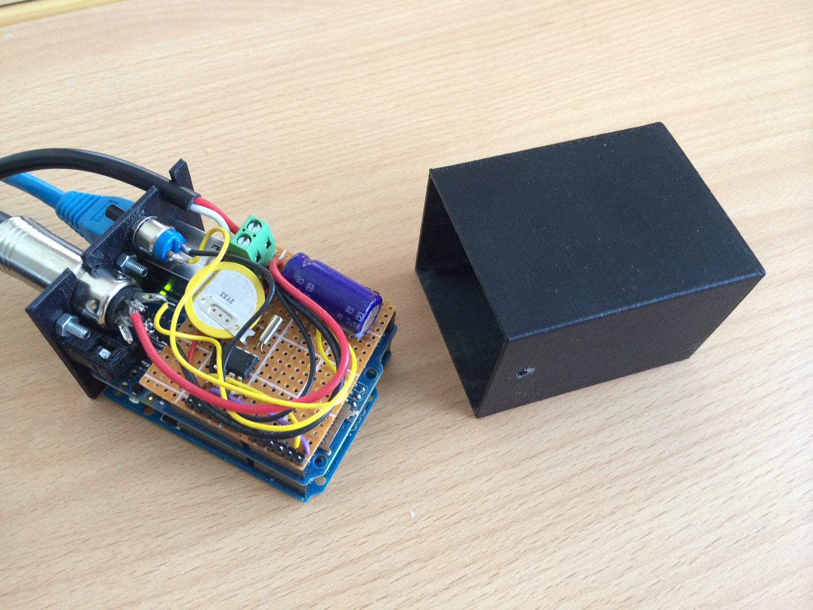 I made a small plastic box using the 3D printer to hide the circuit. The model is here for the box and here for the lid (source). Both parts are closed using a screw and a nut. Once everything is done, only the control software is missing.
The software
The control software is divided into two parts: the code running on the Arduino, and the control interface for smartphones. I tried commenting the code properly, do not hesitate to ask questions if necessary.
The Arduino code
The Arduino code is available on Github. It used the Adafruit NeoPixel library to control the strip and the Time and DS1307 libraries to keep track of time. The standard Wire library is also used by DS1307. Finally, the standard Ethernet library is used to implement a web server listening to requests sent by the control interface. The web server answers only on one address: http://ARDUI.NO.IP.ADDRESS/setMode?MODE_PARAMS. ARDUI.NO.IP.ADDRESS is the IP address automatically attributed to the Arduino using DHCP. To know it, one only has to push the button on the controller. The address then slides on the display. MODE_PARAMS is a string allowing the Arduino to know which mode should be displayed. To allow the interface to send requests to the frame, the header “Access-Control-Allow-Origin: *” is inserted into each reply. It allows any website to contact the frame directly. The code is divided into different classes, with a header and implementation file each:
- The RTCControl class is based on the DS1307 library. But it also contains the ability to access the RAM of the RTC chip. Indeed, the chip contains 56 bytes of unused RAM memory. These bytes are used by the frame to save the last displayed mode, so as to start with this mode next time it is powered on.
- The WebServer, WebRequest and WebResponse classes form a generic dynamic web server reusable for other projects.
- The Pixels class simplifies the LED addressing by using (x, y) coordinates instead of the number of the LED on the strip.
- The cadre.ino file uses all these classes to let the frame work.
The smartphone interface
The smartphone interface is actually built as a simple website. It is available on Github. You can see it work here. Once downloaded the first time, the interface works without Internet connection thanks to the HTML5 offline features. Everything is done on the client side in javascript. The first time, the IP address of the frame has to be entered by clicking the plus in the top right corner. Settings are saved for next uses. Requests are sent to the frame to change its mode. So the smartphone has to be able to access the frame through the IP network.
The interface is optimized for the iPhone but also works on Android.
The interface is not served by the Arduino, instead it is hosted on an external server. I tried hosting it on the Arduino, but it is way too slow.
For most modes, the interface simply sends the displayed settings (colors, text…) to the frame, but in “clock” mode, the interface also sends the local time of the smartphone. This way, the RTC clock is set automatically every time someone sets the frame in “clock” mode.
To improve
The frame works very well in its current state, but like any project, it is never really finished. Here are some details that I would like to improve. If you have ideas, do not hesitate:
- The grid used to separate pixels is not perfect. Printed parts are not really straight. And the grid is divided into 4 parts, with some open pixels on the sides that are closed by another part. This should be modified to prevent the light from going through the small holes created.
- The LEDs do not work at their maximum capacity! They draw at most 3.6A, while they should be able to draw up to 8A. This is probably due to the cable I use between the controller and the display, which should be bigger.
- The frame can become quite hot when it is against a wall, I am not sure yet how I could fix that.
You are up!
Do not hesitate to use this project, copy it, modify it, and keep me informed in the comments. I will update the article if things evolve.